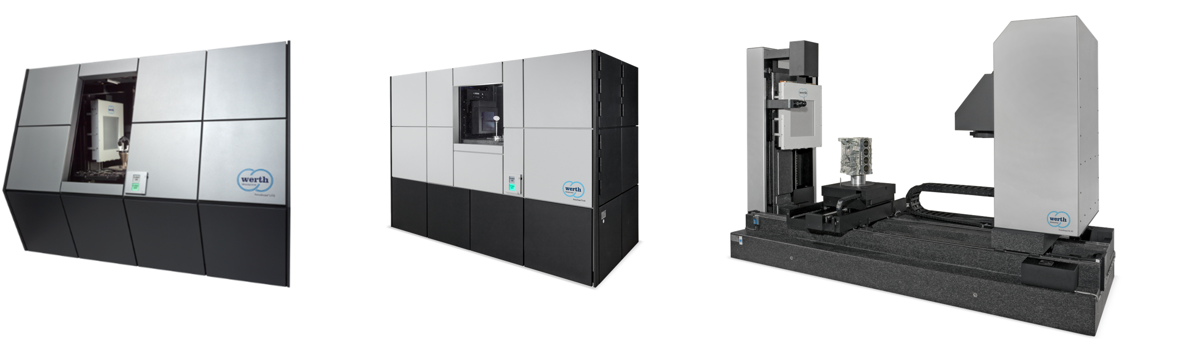
Werth Coordinate Measuring Machine with X-Ray Tomography Sensor TomoScope® S Series

Werth Coordinate Measuring Machine with X-Ray Tomography Sensor TomoScope® S Series

Category: Industrial CT-Xray Machine Available
Purchasable on official site
For more information, visit our official website at mspmetrology.com

Description

TomoScope S

Coordinate Measuring Machine with Tomography Sensor (Compact Design)

Features

Complete, Precise, Non-Destructive Measurement

Ever since Werth presented the first X-ray tomography machine developed especially for coordinate measuring technology, with optional multisensor systems, the machines in the Werth TomoScope® series have enabled the complete, precise, and non-destructive measurement of workpieces. This technology minimizes first article inspection times for rapid product validation, thus reducing development costs. Special measurement methods also make it possible to monitor processes with high throughput due to short measurement times.

TomoScope S

3D CT Measurement

Multisensor coordinate measuring machine for 3D measurements with computed tomography (CT).

Rigid Granite Base

Rigid granite base with precision linear guideways and integrated rotary axis.

Protective Shielding

Fully protective lead shielding design according to German Radiation Protection Act.

Positioning Aid

Optical workpiece positioning aid for easy positioning of the measuring objects.

WinWerth® Software

Graphically interactive, user-friendly measuring software for efficient measurement workflows.

Subvoxeling

Local subvoxeling for reduction of the probing error.

Options

  • Second Z-axis for operation in multisensory mode (patent pending)
  • Workpiece changing system
  • Raster tomography (patent pending): measurement of small features, even on large workpieces, with high resolution and extending the measurement area
  • Multi-ROI tomography for high resolution measurement of small object details at any position in the measurement volume in the same reference system (patent)
  • Volume cross section image processing for evaluation of cross sections directly in the voxel volume (patent pending)
  • Spiral CT for reducing cone beam artifacts
  • OnTheFly tomography to significantly reduce the measurement time
  • Multi-spectra tomography to minimize artifacts when measuring multi-material workpieces
  • Werth Tool Correction (patent) for direct correction of the injection mold
  • Werth Autocorrection (patent pending)

CMM Technology Inside

Coordinate measuring machine technology built into the CT measuring platform.

CAA Compensation

Compensation support for precise measurement workflows.

Temperature Compensation

Temperature compensation helps support stable measuring results.

Pre-Calibrated Magnifications

Pre-calibrated magnifications support repeatable CT measurements.

Fully-Automatic Measurement

Automatic measurement without manual influence on the measuring results.

Artifact Correction

Integrated artifact correction with accuracy around 2 µm − 20 µm depending on component material and geometry.

Principle

Principle

X-ray images of the workpiece are taken at various rotated positions. With suitable mathematical methods, they can be used to calculate a complete, high-resolution volumetric model. A patented subvoxeling process determines the measurement points at the material boundaries.

3D Comparison

The 3D point cloud can be compared directly with the 3D CAD model, imported for example in IGES or STEP format. Each point is automatically associated with the corresponding patch in the CAD model. WinWerth® measuring software generates a color-coded deviation plot for each measurement point in comparison with the specified CAD surface.

3D Comparison
Dimensional Measurements

Dimensional Measurements

The points associated with a geometrical feature are selected for analysis, either using automatic segmentation or simply by clicking on the CAD model (patent). WinWerth® calculates the corresponding standard geometrical features (line, cylinder, plane, etc.) and links them into dimensions, generating a measurement report on request. Using virtual planes, measurements can be performed in any cross section of the volume or point cloud (patent pending). Workpieces made of several different materials can be measured using this technique.

Machine Design

The design principle of the CT machines, based on proven components from Werth coordinate measuring machines, ensures stability and precision. All TomoScope® and TomoCheck® machines meet the requirements to be considered cabinet X-ray systems.

Machine Design
Precision in the Sub-Micron Range

Precision in the Sub-Micron Range

The CT measurements can be traced back to the internationally recognized length standard of the German National Metrology Institute (PTB – Physikalisch-Technische Bundesanstalt), using calibrated standards in accordance with VDI 2617 or VDI 2630, with a DAkkS calibration certificate available on request. CT measurements, e.g., on plastics, can be performed with measurement errors of a few micrometers. If precision in the sub-micron range is required for workpieces that are difficult to penetrate radiographically, multisensor systems can help reduce systematic measurement errors due to artifacts, using patented Werth Autocorrection.

Special Measurement Methods

Special measurement methods, such as OnTheFly CT, Eccentric CT (patent), Multi-ROI CT, Raster Tomography, and Dual-Spectra CT are available to increase the measuring speed or resolution, to expand the measurement range, and to measure workpieces made of multiple materials.

Special Measurement Methods

X-Ray CT Speeds Up First Article Inspection

The measurement time for first article inspection of a workpiece has been reduced from several days, using classical measurement techniques, to a few minutes with CT. Product development can thereby be sped up significantly, which increases cost-effectiveness. With extensive and precise information about the workpiece, mold corrections can be implemented in a fraction of the time.

X-Ray CT Speeds Up First Article Inspection

WinWerth® Software

The operation of machines with a wide variety of sensors, but also the evaluation of volume data and point clouds are possible with WinWerth® in a unique combination. The Werth image processing software is based on 40 years of experience and is the foundation of probably the most powerful image processing sensors for coordinate measuring machines currently available. Optical distance sensors, conventional styluses in single-point or scanning mode, the Werth Fiber Probe®, X-ray computed tomography or machines with a combination of several sensors are all supported by the uniform concept. Measurement points, 2D images or volume data can also be conveniently evaluated in terms of geometrical characteristics or with part-to-part deviation analysis. PTB-certified evaluation algorithms ensure correct measurement results. All desired information is displayed in the graphic: CAD models with PMI data, voxel volumes, measurement point clouds, colour-coded deviation plots from 3D nominal-actual comparisons, video images, measurement and calculation elements as well as flags with nominal and actual values, tolerances and deviations. In order to meet the most diverse requirements, the software has a modular structure. Various machines can be operated, from simple measuring projectors to complex multi-axis coordinate measuring machines with multi-sensor systems or even X-ray tomography sensors.

WinWerth Software
Image Processing Measures almost by Itself

Image Processing Measures almost by Itself

The “intelligence” of the WinWerth® measurement software then takes over, for example, the exact determination of the object area to be captured, the selection of the geometrical element to be measured (e.g. straight line, circle, corner point) as well as the linking algorithms for determining geometrical characteristics such as distances, angles and diameters.

Measurement Points Distributed Automatically

Measurement points or scan lines are automatically distributed on the geometry elements to be measured, e.g. as circles, cylinder surface lines, stars or spirals, taking into account the necessary travel paths. In this way, the complete measurement sequence, including evaluation, is first created offline using the CAD model or online with the minimum number of points for the respective geometry element.

Measurement Points Distributed Automatically
Evaluating Images Perfectly

Evaluating Images Perfectly for Optics and Computer Tomography Scan

The evaluation is mainly realised by PC hardware and software. In a first processing step, the image can be improved with image filters (optimising contrast, smoothing surface disturbances). This enables reliable measurements even with difficult edges and rigid scanning in incident light.

Testing and Changing Made Easy

The feature tree in the WinWerth® user interface also controls the test and change mode, in which programmes can be run step-by-step and changes can be added. A text editor, available in parallel, allows experienced operators to directly enter or change DMIS programme code while teaching in programmes.

Testing and Changing Made Easy
CAD-Online and CAD-Offline

CAD-Online® and CAD-Offline®

Measurement programs can be generated both online and offline using 2D or 3D CAD models. The CAD models are imported in either STEP, native CAD or IGES format. In offline mode a sensor is selected and a patch or combination of several patches is selected on the CAD model. The software computes the necessary actions for the sensor and automatically generates the corresponding segment of the program. The graphic shows the simulated measurement sequence. In online mode the procedure is similar to the offline mode, but the coordinate measuring machine immediately performs each operational step so it can be observed live.

Full Specifications

Model TomoScope S
General
Machine Type Multisensor coordinate measuring machine with CT device
Probing System Compact X-ray sensor, Optical Sensors, Image Processing, Mechanical Probing Systems: Trigger and Scanning Probes
Modes of Operation Linear path control
Measuring Software WinWerth®
Operating System MS Windows
Detector Options
Description Number of Pixels / Pixel Size Max. Part Dimensions
X-DETECTOR PE1000 1000 x 1000 / 200 µm In the image: ∅ = 154 mm / L = 181 mm; Raster Tomography: ∅ = 204 mm / L = 339 mm
X-DETECTOR VA2000H 1874 x 1496 / 127 µm In the image: ∅ = 178 mm / L = 176 mm; Raster Tomography: ∅ = 178 mm / L = 361 mm
X-DETECTOR VA2000V 1496 x 1874 / 127 µm In the image: ∅ = 150 mm / L = 223 mm; Raster Tomography: ∅ = 190 mm / L = 378 mm
X-DETECTOR VA2000/4V 1792 x 2176 / 139 µm In the image: ∅ = 180 mm / L = 227 mm; Raster Tomography: ∅ = 180 mm / L = 424 mm
X-DETECTOR TD3000V 2930 x 3096 / 99 µm In the image: ∅ = 212 mm / L = 233 mm; Raster Tomography: ∅ = 212 mm / L = 419 mm

Contact us today to inquire about the TomoScope S and enhance your coordinate measuring and tomography inspection capabilities.

More detail about MSP Metrology (M) Sdn Bhd
MSP Metrology (M) Sdn Bhd
MSP Metrology (M) Sdn Bhd Precision Measuring Equipment Supplier in Malaysia & Singapore | Metrology & Material Testing Supply JB, KL & Penang - MSP Metrology (M) Sdn Bhd
Contact Us flagMalaysia